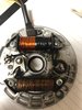
Damn, you have a good eye. Tightening up the lower stator screw along with loosing the top coil and pulling down to get every bit of the slop out has taken 99%, if not 100%, has cured it. Will check again tomorrow with fresh eyes. I was able to confirm that I have enough clearance without removing timing mechanism...at least on this mitsu. Assuming fresh eyes confirms it, will put it through the paces tomorrow.
Impressive set of eyes you you have!
Impressive set of eyes you you have!
")
")