You are using an out of date browser. It may not display this or other websites correctly.
You should upgrade or use an alternative browser.
You should upgrade or use an alternative browser.
Adding a LED to an aftermarket large housing.
- Thread starter Deoodles
- Start date

I used the key I had and went out last night. I didn’t use high beam much, I didn’t need it. I did leave it on to see what oncoming traffic would say. I was flashed by oncoming traffic. ") It can light up an entire block. The battery was 12.4 v when I left. I stopped to feel the reg twice. It never got past cool in the hour I was out. When I returned I measured the battery again and was at 12.7 volts. I’m starting to think this worked. Next week I would like to figure out wattage. It will be helpful to know when I need to replace bulbs in the future. All in this probably ran me C note. Well worth it IMO. On the down/bright side. I was able to source another one of these setups. New in box stator,flywheel, CDI, and coil. It was meant to be a CT70H 6volt to 6volt CDI conversion. But it will produce 12 volts reliably for years just by using a 12 v reg/rec. it was pricy at 200 but it’s something I want in my stash.
It can light up an entire block. The battery was 12.4 v when I left. I stopped to feel the reg twice. It never got past cool in the hour I was out. When I returned I measured the battery again and was at 12.7 volts. I’m starting to think this worked. Next week I would like to figure out wattage. It will be helpful to know when I need to replace bulbs in the future. All in this probably ran me C note. Well worth it IMO. On the down/bright side. I was able to source another one of these setups. New in box stator,flywheel, CDI, and coil. It was meant to be a CT70H 6volt to 6volt CDI conversion. But it will produce 12 volts reliably for years just by using a 12 v reg/rec. it was pricy at 200 but it’s something I want in my stash.
It can light up an entire block. The battery was 12.4 v when I left. I stopped to feel the reg twice. It never got past cool in the hour I was out. When I returned I measured the battery again and was at 12.7 volts. I’m starting to think this worked. Next week I would like to figure out wattage. It will be helpful to know when I need to replace bulbs in the future. All in this probably ran me C note. Well worth it IMO. On the down/bright side. I was able to source another one of these setups. New in box stator,flywheel, CDI, and coil. It was meant to be a CT70H 6volt to 6volt CDI conversion. But it will produce 12 volts reliably for years just by using a 12 v reg/rec. it was pricy at 200 but it’s something I want in my stash.I can explain the floating (un-grounded) stator. With a single-coil/2-pole (6v type) stator, both ends of the coil winding are fed to the reg/rec unit, one to each input. With a radial array, each coil in the array is wound in the opposite direction (CW-CCW) from one, continuous, length of wire, leaving two end leads...each of which is wired to the reg/rec unit same as with the single coil type.
The reg/rec unit, itself, provides the system ground and that's key to its operation. Full-wave can generate high voltages, which requires tight regulation. The reg/rec dumps excess voltage to ground.
With the "normal" half-wave/"balanced" charging/lighting systems used on virtually every engine out there, one end of the coil is run to ground...leaving only a single output, that is either fed to a simple diode or directly the the HL circuit. The 6v alternator lighting/charging coil is actually two coils wound on the same armature, each has one end run to ground. These half-wave systems generate less voltage and rely on total system draw (bulb wattage and battery) to regulate voltage...it's as crude as it sounds, depending on matching (a.k.a. "balancing") system draw to maximum alternator output.

That’s it. Racers explanation is spot on. See post # 143. The drawing the 3 poles of the stator A,B, and C grounded.
Look at the first picture in post 165. All 3 poles wound with no ground. A was wound like B and C, just 1 25’ length per pole. 75’ total ccw,cw,ccw
Last edited:
ez50
Well-Known Member
Alright, I get this much. I have a TT 150. Now how about the ground functions on a stock K1? Horn, neutral light and brake lights work on frame grounding to light them. Do you just ground the battery to the frame? Add to the list turn signals for my K3. I hope everything doesn't need to be isolated.
Next week I would like to figure out wattage.
Your resistors are going in the mail in the morning. From your trial runs, it sounds like everything is work as expected and much better than before.
As far as the original Rec/Reg, going from memory, it had a diode or 2 inside that clamped the yellow winding to battery voltage. By clamping, would not allow the AC waveform to go any higher. The other winding for charging the battery was not a FWB circuit for sure. Never figured out the guts of this widget, but it did top out at about 2 to 2.5 amps. It was like Scotty on Star Trek "giving all it's got Captain".
In your situation, I would expect you've got a solid 50-60 watt setup, maybe more. When you get the resistors and get them connected, will gladly walk you through being able to get close to what you have. Regardless now that you're all LED, you have a lot more capacity in the stator & Rec/Reg that you have load.
Alright, I get this much. I have a TT 150. Now how about the ground functions on a stock K1? Horn, neutral light and brake lights work on frame grounding to light them. Do you just ground the battery to the frame? Add to the list turn signals for my K3. I hope everything doesn't need to be isolated.
Okay, to be clear here, if your lighting coil is untouched, it's grounded and this unit absolutely will not work. With a grounded lighting coil, all current will be dumped to ground and you'll have a total loss electrical system. Only way I know to get an ungrounded 6v lighting coil is to rewind it.
Your resistors are going in the mail in the morning. From your trial runs, it sounds like everything is work as expected and much better than before.
As far as the original Rec/Reg, going from memory, it had a diode or 2 inside that clamped the yellow winding to battery voltage. By clamping, would not allow the AC waveform to go any higher. The other winding for charging the battery was not a FWB circuit for sure. Never figured out the guts of this widget, but it did top out at about 2 to 2.5 amps. It was like Scotty on Star Trek "giving all it's got Captain".
In your situation, I would expect you've got a solid 50-60 watt setup, maybe more. When you get the resistors and get them connected, will gladly walk you through being able to get close to what you have. Regardless now that you're all LED, you have a lot more capacity in the stator & Rec/Reg that you have load.
I would think that using different bulbs would be a crude-but-effective test methodology. Automotive headlight bulbs are commonly 55-65W. I wouldn't try using one, for real, due to the heat they generate. But a short-duration test should tell you a lot before anything (like the wiring inside your HL shell) can be cooked. If you're getting 55W, then powering-up a 65W bulb should pull charging voltage well below 12.8V.
I would think that using different bulbs would be a crude-but-effective test methodology
Absolutely. The easiest and best way I can think of.
Next week I would like to figure out wattage.
As a suggestion, you can swap the tail light lamp back to an incandescent 1157. This will add 35 watts of load if you press the brake pedal. If it turns out you need more, can swap out the HL bulb as well. Personally, if your combo continues to charge the battery with the TL & BL on in addition to your other lamps, my opinion is you're in good shape.
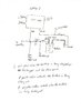
Working on a crude wiring diagram as we speak to show you where to insert the resistor.
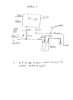
Ray. Here's a couple of ROUGH sketches to give you a couple of ideas of where to install 0.1 ohm resistors that are on the way to you. I'm assuming that that you'll want to minimize your checks or else you'll be driving a test machine where it's by-product becomes a mode of transportation
Personally, I would go with option 2 and keep adding load (old incandescent bulbs) until the battery is no longer being charged. With a couple of checks, and added bulbs, I think you can get close to determining what your system can handle using just 1 resistor. Once you digest my chicken scratching, will give you a few more tips of what to expect.
I looked at your schematic but a schematic does not necessarily show how it's physically wired. For example in option 2, the resistor needs to be inserted between the battery and the first connection point to everything else. Also, I'm assuming/hoping that you do in fact have 2 wires on the positive lug of the battery? One large wire for the starter and a 16-20 gauge for everything else?
Attachments
Absolutely. The easiest and best way I can think of.
As a suggestion, you can swap the tail light lamp back to an incandescent 1157. This will add 35 watts of load if you press the brake pedal. If it turns out you need more, can swap out the HL bulb as well. Personally, if your combo continues to charge the battery with the TL & BL on in addition to your other lamps, my opinion is you're in good shape.
Working on a crude wiring diagram as we speak to show you where to insert the resistor.
Hadn't realized an 1157 bulb drew quite that much. I agree with you, as in I'm practicing what I preach with this...the system, in my bike, has had no problem keeping up, even charged a drained battery...all lights on...in a 90-minute ride. That's been good enough enough for me, though I'd like to know how much output the system has.
One testing caveat is that a charged battery can power an automotive headlight with nary a trace of distress...for a time. Best, educated guess, a 55W bulb would need somewhere between 30-60 minutes to drain a 12v/5.0ah battery, engine off. Running a partial-loss system could stretch that out more than enough to lead one to a faulty conclusion. A relatively small (5-20W) charging deficit, wouldn't discharge the battery for hours. For example, at -10W, there's ~5 hours of usable current, before the battery is discharged. Since 5-hour rides are kind unusual, this could take days, or weeks, to manifest. At the same time, the reg/rec needs a healthy battery to operate normally. Hence the suggestion to monitor system voltage.
There is no starter it looks like I can put the resistor in line with the fuse???? I’ll look at this again
You're golden if no starter and just one wire coming off the positive post. Just put the resister in series and you're good to go.
That's been good enough enough for me, though I'd like to know how much output the system has.
It's easy enough to get close just by using 1157, 1129 (turn signal bulb) or headlight lamps. Continue to add load until the battery is discharging then find when it's charging vs. when it's not. The capacity is somewhere between these 2 points.
I normally test in increments of 2,000 RPMS (2,4,6,8), but 4k and 8k paints the picture.
I picked up an "electronic rheostat" for lack of a better term on the cheap, where I can preciesly dial up the load (increase the resistance) until battery charge/discharge current/voltage is zero. By zero, I mean the battery is not being charged or discharged. Very accurate and way over kill but it helped me find the max capacity without a lot of hassle....and time. It has a display (voltage, current and power) that I use to double check my Fluke meter.
You're also correct about battery condition. Seen this first hand. I encountered a battery that seem to be ok, but was not. It would charge up in no time but drop off in no time as well. I do know that the more healthy the battery is, the less strain it puts on the stator and Rec/Reg. Long boring story for another day.
Battery is 14.6 v cold sitting 2 days. I plugged in a Harley 40w LED headlight. On high beam the battery went down to 12.0 v. I started the bike and the battery went to 12.6 v. I adjusted the reg and at 3k the battery went to 14.2v. I set it back up and readjusted the system volts back to 12.8 v. I was pulling close to 50w total and still had 14.2v. Did I do that right?


Last edited: