Lighting question

andrewdell19

Active Member
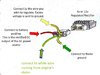
On my k3 with piranha engine, with the wires all booked up (one yellow grounded, and one yellow split between the yellow on DRATV harness, white on DRATV harness, and yellow of rectifier from DRATV) my head light now works when the battery is on but engine is not running. I know my stock ct70 doesn't have headlights on when its not running, only tail light etc.

I checked in the headlight bucket, and brown/red are connected to brown/red bullet connector, and same with red- connected to red bullet connectors. All colors line up in the headlight bucket.

Now what could be making the headlight now work? DRATV believes that the light should only run off the engine and not the battery, and of course he has more experience than I do so what do I have messed up if this is happening?

Here are the parts I used:

https://tboltusa.com/store/piranha-140cc-engine-br-fits-pit-bikes-and-other-minis-p-660.html
http://dratv.com/ct70.html
http://dratv.com/ctsubcdiwiha.html
http://dratv.com/12vrerepikea.html
http://dratv.com/6voregre.html

Now when the bike is running and lights are all on, I am getting 7 plus volts across the battery terminals which is what DRATV indicated is normal and expected. Now I have run the bike for about 5-10 minutes with lights on and I believe the lights are not getting dimmer, and that the motor and rectifier is recharging the battery fast enough to keep the head lights on... So while I don't want to fix anything that is not broke, I want to learn more about electrical and learn what I did to mess it up in that the head light should only work when the engine is running and in the 3rd position but it currently is set up that when the key switch is in the current 3rd position the head light comes on.

Another issue I have is that the blinkers don't flash, they come on but don't flash... and I read that could be because the neutral light is not working in the speedo... I believe that is because the DRATV harness doesn't have a neutral wire on it therefore the neutral light is not working... I am going to pull the tank this weekend and see if I can hook up that neutral wire off the piranha to the neutral in the original Honda wiring harness.
 

kirrbby

Well-Known Member
I would have to study the original harness wire diagram to try to trace it all down, but it seems to me that you now have ALL of the lighting running off of the battery circuit. So, ALL of the lighting must be spliced or tied in together somehow. And that makes sense since you are only using one wire from the stator for lighting power. If you track the wires from each light, one at a time, I imagine they all lead back to that one yellow wire from the stator somehow...when the switch is in the 3rd position.

I definitely agree, don't fix what ain't broke. Especially since it seems that you now have a BETTER setup than the one you were expecting.
Your 6v battery matches your 6v regulator, so that IS correct.

But if the blinkers don't blink...that is a problem. Are you using the stock flasher? I think you might need to upgrade it to a...electronic?? one? You need plenty of power to make the old style flashers work. Tru unplugging the HL and TL, then see if it blinks when it's getting more juice.
 

kirrbby

Well-Known Member
I would definitely like to look closely at how your setup "works"...the setup where one yellow gets grounded.
I have that same 2 yellow stator on my lil blue z50 that I never did get the lighting figured out.

I'm thinking that the lighting circuit on that type of stator is NOT grounded to the engine(stator plate) at all...unless you ground it yourself. So the 2 yellows would be like both ends of a single strand of insulated wire that's wound around the stator posts. I forget what they call that, but I could find it in my thread somewhere. I called TrailTech looking for help. They told me that their stators we're all x type and not grounded. Or it might have been their regulators that I asked about...lol, can't remember now.
I'll look it up when I have time.

This thread...somewhere.
https://lilhonda.com/index.php?threads/first-time-adding-displacement.14697/page-6

#149
 
Last edited:

andrewdell19

Active Member
Hey Kirrby. Thanks for the reply. So i physically grounded the yellow wire using some extra wire I had and grounded it to the air filter bokt hole that would attach the top of the air filter to the frame that i now have the 2 i to 1 petcock bolted to.

I have tried using the stock 6v flasher along with the 12v flasher that came with 12v set up. I have found one that supposedly uses considerably less energy to power so I may just buy that and test it out.

Have you heard anything about if the neutral light bulb or any other light bulb out in the speedo that the blinkers wouldnt physically flash but stay on?
 

kirrbby

Well-Known Member
The stators with 2 yellows are the "floating ground" type. I was told that some pitbikes have the motors that are mounted in rubber, so the engine is not grounded to the frame. In that case you have to run the power AND the ground, to each light, direct from the stator.

But our bikes engines ARE grounded to the frame. The lights, most, get their grounds from the frame. Turn signals, and TL/BL, only have one wire running to them which supplies power, they get the ground from the frame thru their mounting, or a wire jumped from their mounting to the frame.

That changes how the, 2 yellow wire, stators work.

If you were to use both of those yellows as 2 separate power supply's, on our bikes, you would have to "float the grounds" to each light.

We need JPardue to pipe in here... Or maybe adamnlv...racerx...dirtbiker188...allenp
 

andrewdell19

Active Member
Yeah man... I'm going to keep running and see what the numbers look like. But with 65 mph winds going today and tomorrow I think Sunday May be the first day to run for any extended period of time (more than 10 mins). But just got some one piece rims and going to measure them and see what tires I can rock. But I think I'm going to stick with 4x10... Rim measures just over 3 inches wide tho so that has me a little concerned about running greater than a 4x10
 
Last edited:

OLD CT

Well-Known Member
Dratv's harness ''does'' show the neutral wire. Check out the pic, it's the green with red stripe wire right above where he circled the ''wire to coil pickup'' in his harness pic. Not that I am saying that if it isn't hooked up it would cause the light issue. If your lights are on without the bike running you may have to double check the headlight ''and'' hi/lo beam HL switch wiring. One time, I managed to get a bone stock ct's lights to come on in the first position with the bike off, with the hi lo switch wiring on a K1. I had the switch wiring wrong. I am trying to remember the colors, oh yea, blue and white.
 

allenp42

Well-Known Member
I don't have any experience with Piranha, Lifan or any of the aftermarket engines, but I'll try to help. I've looked at some some of the wiring diagrams at Tbolt and I'm not quite sure what you have. So with that, I've got a few basic questions.

How many wires do you have coming out of the Stator? I would assume a wire for the ignition, and maybe 2 for the lighting/charging?

Regarding lighting/charging, I've seen 2 diagrams where both wires were yellow. However, in one wiring diagram I saw, it was a single coil with neither side grounded. Another shows a coil with the center tap grounded....and 2 yellow wires coming out. Do you have access to MultiMeter? It's easy to find out out what you have in the stator by taking a few resistance measurements.

Unplug the stator from the harness and measure the resistance (lowest scale) from each yellow wire to ground. If it's a single coil, it should read "open" as in very high/infinity resistance. If it's center tapped, you'll probably see about 1 ohm or less.

If I can better understand your stator, maybe I'll be able to help you with the other stuff.

Allen
 

andrewdell19

Active Member
Dratv's harness ''does'' show the neutral wire. Check out the pic, it's the green with red stripe wire right above where he circled the ''wire to coil pickup'' in his harness pic. Not that I am saying that if it isn't hooked up it would cause the light issue. If your lights are on without the bike running you may have to double check the headlight ''and'' hi/lo beam HL switch wiring. One time, I managed to get a bone stock ct's lights to come on in the first position with the bike off, with the hi lo switch wiring on a K1. I had the switch wiring wrong. I am trying to remember the colors, oh yea, blue and white.

Yes 100% my fault... the pirahna engine doesnt have a neutral indicator wire.

Yeah the hi lo switch has a blue and white wire running into head light bucket and both connect to the head light one going to the dual blue bullet connector and one going to the single white bullet connector. Then brown/red wire that i believe powers the hi low switch is connected to the brown red bullet connector.

So yeah sounds like you had the ct at one point running off the battery to power the lights... if I am understanding you correctly you had the hi low dimmer switch not wires correctly? Do you remember how you had the wires hooked up? Maybe that can shed some light on what I may be missing.
 
Last edited:

andrewdell19

Active Member
I don't have any experience with Piranha, Lifan or any of the aftermarket engines, but I'll try to help. I've looked at some some of the wiring diagrams at Tbolt and I'm not quite sure what you have. So with that, I've got a few basic questions.

How many wires do you have coming out of the Stator? I would assume a wire for the ignition, and maybe 2 for the lighting/charging?

Regarding lighting/charging, I've seen 2 diagrams where both wires were yellow. However, in one wiring diagram I saw, it was a single coil with neither side grounded. Another shows a coil with the center tap grounded....and 2 yellow wires coming out. Do you have access to MultiMeter? It's easy to find out out what you have in the stator by taking a few resistance measurements.

Unplug the stator from the harness and measure the resistance (lowest scale) from each yellow wire to ground. If it's a single coil, it should read "open" as in very high/infinity resistance. If it's center tapped, you'll probably see about 1 ohm or less.

If I can better understand your stator, maybe I'll be able to help you with the other stuff.

Allen

Hey Allen.

I have two yellow wires, a blue wire, black wire, and green wire on the pirahna engine. Unplugging the two yellow wires, grounding one end on the engine and touching the red end to each yellow wire on the bullet connector has a reading of 1 all the way on the left of the multimeter screen. Touching the two probles together reads 001 to 003 or so. Therefore I think it is reading open and one yellow wire needs to be grounded which I have done now. Previously when one yellow wire was not grounded the battery would lose voltage as I rode it or as the engine ran with lights on. And now that one yellow wire is grounded I believe it is not losing voltage and its been recharged at a good rate since after riding I am still reading over 7 v across the battery terminals (touching black probe to negative and red to positive).
 

allenp42

Well-Known Member
Hi Andrew,

Based on your measurements, I think you have a single/non center tapped coil for lighting and charging. I'm also assuming that you're using the 6v regulator and pig tail per the attached drawing?

It sure smells like "something" in the wiring you added has connected the yellow wire in your CT to red/white wire in your CT? That is the only way I can fathom that the headlight burns in 1st position of the key switch.

Regarding the pig tail on the regulator you added, is the red wire on the pig tail connected the red/white in the CT? One of the green wires to ground, and the green wire labeled "connect to white wire coming from engine's stator" to the yellow wire from your stator? Is the yellow wire on the pig tail connected? If so, where? I am asking questions just to get a better understanding. This is my first rodeo remote cyphering something I've never seen before.

Also, is the attached drawings one of the sketches you're using?

Allen
 

Attachments

  • 6 Volt Regulator DRATV.jpeg
    6 Volt Regulator DRATV.jpeg
    218.5 KB · Views: 101

allenp42

Well-Known Member
....or the regulator wire that connects to the yellow wire in your CT (lighting circuit) is just a regulated pass through of battery voltage? Going to sleep on it, but to humor me, when you have time, disconnect the wire you connected to the CT lighting circuit (yellow) at the CT end, and measure the voltage coming out of the regulator with the key in the 1st position, engine not running.
 

allenp42

Well-Known Member
I have been looking at various stators used on many of the aftermarket engines. If in fact your coil is a single winding type with no center tap - i.e.: no separate wire for charging and another lighting, I'm think what you're seeing may be normal. If I am correct and your measurements are correct -and- you want the lighting to work as before, then I think you'll need to make some changes. Either add another regulator and connect it to the same yellow wire from the stator and do some experimenting.

The 6V regulator you're using appears to be based on regulating the charging voltage and lighting voltage from a stator with 2 outputs. In your case, you only have one output....so you don't have a stator output connection for the lighting circuit?

Just for my own education, when the engine is running, could you measure the AC voltage on the yellow wire are various outputs? Just want to confirm that it is a ~12v ac and just how high it goes.

From Tbolt site - "For YX Stators with 2 yellow auxiliary leads (not 1 yellow and 1 white ), you will need to Ground ONE Yellow lead and use the other Yellow Lead as your Output."

https://tboltusa.com/store/tech.php?pID=57/Wiring+With+Lights

Again, my experience on AFT engines and wiring conversion kits is limited, so don't take what I think as the absolute truth.
 

andrewdell19

Active Member
Hey Allen,

I aporeciate you taking the time to think about this.

The lighting works when engine is not running in the second or last position. No head light if the key is up one switch regardlesd if engine is running or not.

Yes I am using everything on the DRATV link, his regulator to convert 12v to 6v, his regulator pigtail, and his subharness. (All very good quality dont let this mishap deter anyone from purchasing these items).

One of my yellows is currently grounded. The other yellow to split into the yellow on the subharness as well as one to the white in subharness. The yellow for the regulator is also spliced into the yellow of the subharness so really that one yellow wire from the engine goes 3 places- to the white in subharness, to the yellow in subharness, and then spliced into the yellow of the regulator harness.

And yeah I certainly can take additional measurements. I think it would be ideal to get the headlight running off the engine like stock ct70 bikes do but if more riding determines my battery is infact charging at a good enough pace to keep the lights bright then I may just stop wondering hahaha. There is another harness out there that is specifically for the two yellow output wires made by trail buddy that I can use too but why spend $35 more if it aint broke?

Thanks again for the advice and steps on what to test next.
 

allenp42

Well-Known Member
"One of my yellows is currently grounded. The other yellow to split into the yellow on the subharness as well as one to the white in subharness. The yellow for the regulator is also spliced into the yellow of the subharness so really that one yellow wire from the enginegoes 3 places- to the white in subharness, to the yellow in subharness, and then spliced into the yellow of the regulator harness."

Just a thought. Not sure of your skill level but you may want to try putting two diodes in series between the yellow/white connection and the other yellow wire on the regulator (one which feeds the lighting circuit. Would give you some separation between the 2 inputs on the regular.

Not knowing the internals of the regulator is road block for precise science. You would be in the experimenting phase at this point.

If interesting, let me know and I'll pick out a couple diodes for you try and how to connect them.
 
Top