You are using an out of date browser. It may not display this or other websites correctly.
You should upgrade or use an alternative browser.
You should upgrade or use an alternative browser.
K-1 and up speedo disassemble
- Thread starter Robert thran
- Start date
scooter
Well-Known Member
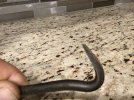
I made myself a tool using cheap Harbor Freight adjustable wrenchto peel back that lip. Get under the lip with the jaws open and then close them up which helps to bend just the lip and not distort the ring. Open it up just enough to get it apart. Small steps working fully around a few times as necessary. I actually have a second one I made with a slightly different tip. I’ll have to find it and get you a picture

scooter
Well-Known Member
scooter
Well-Known Member
Hay I think I have them backwards short tip to get it started. Long one to get all the way under the lip and start undoing the existing 90 deg bend at the creaseThank you
Robert thran
Well-Known Member
Got it… great makeshift tool…thanks Jeff
Robert thran
Well-Known Member
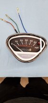
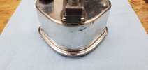
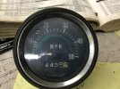
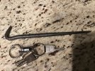
Did you pull yours all apart Or just put the chp decal on? What’s the best way to get the needle off? After eyeing scooters tool and being too lazy to make one I used this and it worked really good..it’s a Mac tool # LP 6 …it’s small but nice sharp edge to grab lip and no damage to speedo body.I copied Scooters tool and it worked GREAT!! Iv rebuilt 3 or 4 speedometers using his design. The hardest part for me is crimping the ring back down. Does anyone have any tricks for that? View attachment 72564View attachment 72565View attachment 72566
Attachments
Clayton
Active Member
I pulled mine completely apart. It’s the original face but it had a piece inside that was broke that I repaired ( the main gear shaft was out of its bearing ) that’s no where near the correct terminology but its all I know lol. The main worm gear was popped out of the hole it’s supposed to be in. I put it back and soldered a small piece to hold it in. While I was at it I turned it back to 0 before I out it all back together.
Great Idea -- I'll be making one in the near future. This should also work on the K0 triangular speedo, correct?
However, it looks like it creates little peaks where the tool edge hits the radius' (see Claytons last photo, at the 7 o'clock position)... Perhaps a plier with a rounded grind on both top-and-bottom mating surfaces, with an "underbite" would be an improvement. (Now I need to find some trashed pliers and try it out).
I'd also like some ideas for crimping the ring back down, for both the K0 unit, and the K1-K4 speedo that Clayton refers to. Thanks!
(perhaps a sticky on rebuilding the speedo, but focused on the hardest part - the ring removal and re-install.)
I can envision a re-install tool for the round speedos, in the opposite configuration of the adjustable wrench. It would be like a 5" C-Clamp, with a custom-made duplicate flanges (eg. die). It would be mirror-imaged on both sides, and have the correct crimp profile. The length of the flanges should be short, about 1", but precisely machined or 3D printed, for the crimp profile. A soft metal for the flanges would be preferable, like aluminum or brass. Much care taken with the tightening of the C-Clamp. You would need to rotate the tool around the periphery a few times to achieve perfection. I need a Bridgeport...
However, it looks like it creates little peaks where the tool edge hits the radius' (see Claytons last photo, at the 7 o'clock position)... Perhaps a plier with a rounded grind on both top-and-bottom mating surfaces, with an "underbite" would be an improvement. (Now I need to find some trashed pliers and try it out).
The hardest part for me is crimping the ring back down.
I'd also like some ideas for crimping the ring back down, for both the K0 unit, and the K1-K4 speedo that Clayton refers to. Thanks!
(perhaps a sticky on rebuilding the speedo, but focused on the hardest part - the ring removal and re-install.)
I can envision a re-install tool for the round speedos, in the opposite configuration of the adjustable wrench. It would be like a 5" C-Clamp, with a custom-made duplicate flanges (eg. die). It would be mirror-imaged on both sides, and have the correct crimp profile. The length of the flanges should be short, about 1", but precisely machined or 3D printed, for the crimp profile. A soft metal for the flanges would be preferable, like aluminum or brass. Much care taken with the tightening of the C-Clamp. You would need to rotate the tool around the periphery a few times to achieve perfection. I need a Bridgeport...
JHminitrails
Well-Known Member
I'm going to eventually build myself something very similar to this. This is an old original tool I found while researching this re-crimping process. Being able to rotate the gauge freely and remain concentric all while keeping the gauge housing under some clamping pressure is definitely the key to a nice crimp, and sealed lens. It's a work in progress for me.Couple things - I ground the shape of the other jaw to control the contact point and where the bend would occur - hopefully close to the original
Bend the flange just enough to get it apart. If you don’t bend it all the way up, it will make tapping it back down easier.
Attachments
JHminitrails
Well-Known Member
Not a Honda tool, but from what I read about that particular tool, it was made by Smith Instruments. I think they are from the UK. I'd love to find one for sale, but I'm sure it would cost a small fortuneThat’s is awesome!! Iv never seen one of those before or even knew that they existed. I wonder if you could ever come across one of those? Is that a Honda tool?
kirrbby
Well-Known Member
I've used a piece...multiple pieces of soft wood to push down and smooth that ring when I put them back together.
I work on a piece of clean plywood so as not to scratch the face side...push down hard to compress the rubber...then just start pushing the ring down...slowly and evenly working around the perimeter until the speedo is CLAMPED back together. Once it's back together, tight seal, I use the wood, dragging it hard against the ring to smooth it out. It's pretty workable if you work slowly and DO NOT KINK anything as you go.
Wood will not scratch that stainless ring. You can use it...kinda like a burnishing tool. Soft pine sticks will actually polish up the metal a bit.
I use sticks of different sizes, and with different shapes on the ends.
Work ALL AROUND the ring...slowly pushing it back until the entire perimeter has been pushed back...then smooth out to look good. Push too hard in ONE spot and you'll kink or dent or over-bend ONE spot.
When you start "burnishing" with the stick, tape around the housing so as not to polish up the zinc finish on the housing. Then you're able to drag the stick against the tape.
Ok...now I'll say...I've never done a round speedo. Only K0 speedos...and only a couple/few. I'm thinking they are easier than round. But still pretty similar process.
Clayton
Active Member
I do nearly the same thing with the rounds speed-O’s Kirrbby, I drilled out a wood block to accommodate the bolts/cables attachment piece so that I can sit the face down on a piece of rubber on my table then place the wood block on top of my gauge and clamp it down to the table. After that I slowly start hammering the trim ring back around. Iv never thought about using wood for that until now but I bet that would work better than a steel punch that I use.
JHminitrails
Well-Known Member
Here's a K0 speedo I restored and crimped manually with various tools. Turned out very well. It's tedious work to make it look good, but definitely achievable with patience. P.S....it is for sale too. 😃