Hi there,
so I took the wire harness out late winter, and been studying for exams recently so never had time to get the bike done by anticipated deadline
I have the harness out on a table: Here is the real problem the dumbass who sold me the bike never used the same colour wiring (well not exactly), but another issue is that I am customizing the harness
1. I only want the "meter light" (the one that illuminates the face of the dashboard), to come one when I hit the light switch on the right handle
2. want the highbeam indicator light to come on when I hit the highbeam switch on the left handle
so now with the wire harness spread out on my table I am trying to simulate the harness (for testing purposes) as if it was in my bike with 12v going through:
which means I connected a 9v power supply dc, and plugged in the relay and cdi and rectifier (trying to simulate)
so I seem to get the meter light bulb to be activated when I hit the switch.
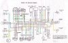
so I connect the orange/blue/grey wires as shown on the diagram (attached), then when I turn the turn sig swith left it cuts out the meter light (meter light goes out)...
How do I get this right? :12::29:
How do I test the flasher relay is working?

ok so I attached the diagram and I colored in the wires b/c it is COMPLETELY different to the stock diagram.
so I took the wire harness out late winter, and been studying for exams recently so never had time to get the bike done by anticipated deadline
I have the harness out on a table: Here is the real problem the dumbass who sold me the bike never used the same colour wiring (well not exactly), but another issue is that I am customizing the harness
1. I only want the "meter light" (the one that illuminates the face of the dashboard), to come one when I hit the light switch on the right handle
2. want the highbeam indicator light to come on when I hit the highbeam switch on the left handle
so now with the wire harness spread out on my table I am trying to simulate the harness (for testing purposes) as if it was in my bike with 12v going through:
which means I connected a 9v power supply dc, and plugged in the relay and cdi and rectifier (trying to simulate)
so I seem to get the meter light bulb to be activated when I hit the switch.
so I connect the orange/blue/grey wires as shown on the diagram (attached), then when I turn the turn sig swith left it cuts out the meter light (meter light goes out)...
How do I get this right? :12::29:
How do I test the flasher relay is working?
ok so I attached the diagram and I colored in the wires b/c it is COMPLETELY different to the stock diagram.
Last edited: